Matching transistor has been least attractive part of amp work. Using a jig to do the job was fall short of joy.
I purchased DCA55 from Alltronics in California ( one of Peak authorized ebay dealer). Item arrived in couple days from purchase and price was right for a hobbyist ($85).
I have been working on Audio Research D-100b amp for few days.It has one channel with blown a pre-driver (2sb555) and a ARC 300026 ( NPN TO3). Because ARC 300026 and 300027 is Audio Research internal pat number of Motorola TO3 transistors, I decide change both channel ARC parts rather than just replace one blown ARC part. I need to find out hfe value for output transistors to replace with modern MJ15024, MJ15025 combinations. DCA 55 was quick and fast and its measurement were repeatable. But I can not say its hfe measurements are accurate because I do not have any other measuring device to compare the measurement accuracies.
DCA55 was some what cursory on Mosfet measurements. It only showed pin names and type of fets. It does not offer other measurement.
For 80 dollars, DCA55 does its job for simplifying transistor matching.
Saturday, July 6, 2013
Thursday, June 27, 2013
My Amp Collections
I think collecting amp is a kind of addictive disease. I know I have too many amps but I can not put my amps on ebay or give to some one -except few I grow to dislike. I am still looking for more amps to get. I do not like brand new amps not because it is expensive but because it does not feel "mine". When I went through all circuitry to find out faults and analyze what each circuit is doing, then I feel it "mine". Some amps I have, cost me more than perfectly working condition of same model because I had to have it at the moment.
When I was young I broke too many watches and radios to satisfy my curiosity. I got my first commissioned work ( I think wage was a cookies) of repairing transistor radio about almost 50 years ago ( 3 rd grade), I used left over copper wire to make home made soldering iron that I stuck into fire to get hot. Then one day, I got bitten by amp bug while I was in middle school. At that time, I made my first real Solid state amp with my own electric soldering iron by following circuit diagram on some magazine article. That was my turning point from tweaking my older sisters beloved Sony 9 transistor radio to all-mine-hifi. From that point. Ever since, I never got cured from amp infection. I do not have formal electronics degree but I can bet you that I spent more time on electronics theory than any electronics college graduate. I worked all my college years ( 4+3+4 )years as audio visual electronic tech on campus and computer networking tech. I do not have computer engineering degree but I can speak few computer languages (php, mysql htmls, some java). I am pretty advanced woodworker with all category of woodworking tools. I built all of my office finitudes and Sam Maloof copies of tables and chairs. Formally, I am an eye doc who has chemical engineering degree.
Here is list of what I use daily;
1) Adcom GFA 585
2)Ampzilla by Great Sound of America(GAS)
3)Rotel RB 1080
4) Parasound HCA1000a
5)Sansui 1000a (Tube)
6) Denon receiver 980
7) Crate Guitar amp ( hybrid)
8) Grace Digital Tuner, Berlinger Cross over, Karaoke DVD, NAS music servers etc..
Here are ones they might hit the sell block; ( they are just collecting dust right now)
1) Scott Stereo Master 340b (Tube)
2) Heath Kit tube amp 32a
3)Carver m1.0t MKII
4)Carver AV405
5) Carver AV505
6)Carver pm 2.0t-1000W but weighs few pounds only.
7) BK ST140
8)Audio Research D-100B
9)Audionic of Oregon BT-2 Pre amp
Here are the list of Ones I am still working on;
1) Marantz 2270 receiver ( restoration in progress, for 2 years)
2)Pass Lab Clone Class A Mosfet ( looking to get case or make one, for 3 years now)
3)Scott Stereo Master 340b- 2nd unit
4)Mark Levinson No. 331
5) Heath kit Tuner/ preamp (tube) - not even started
6) Few junk pro amps ( Crown CE2000, Crown?, Samson?) to fix incase my church needs
7) Bogen Mono tube amp (30w) to convert to guitar amp ( work in progress for 3 years)
After finishing this list, I realized that I definitely Do Not Need any more amps unless I unload some I have on ebay or some where. But prospect of getting new hunky amp all ways raise my pulse. I am very busy with my laptop lurking around web..... I got 3rd degree ampsession.
Wednesday, June 26, 2013
Reparing B&K ST-140 Mosfet Power Amp
I do not know why I need BK ST-140 in my collection. I used to have BK multi channel Mosfet amp and I loved it. I kind like the way BK was built. BK's I had did not show much of cost cutting measures. It was sk mosfet amp.
First impression as I opened BK ST-140 was bit disappointment. It was more of empty box then full built amp. I thought about just using enclosure to house my home made amps. At the end I decide repair it and see if I like the way it was designed.


First impression as I opened BK ST-140 was bit disappointment. It was more of empty box then full built amp. I thought about just using enclosure to house my home made amps. At the end I decide repair it and see if I like the way it was designed.
When I get back from golf on Sunday, I will find out what is fault in this amp.
Update: 4/30/2013
By looking at the amp board I found 4amp fuse on + side of rails on both amp board was newer than - side rails. Some one replaced fuse on +side of rails. This can be sign of shorted both side output mosfet 2sk135 or fault of both rail caps. It is highly unlikely to have both side rail caps fail at the same time or blow both output fets same time. Both side all output fets were checked good (hew!!!).
After disconnecting power supply from amp boards and unscrew power board caps and apply 15v to charge then recheck the voltage in few minutes to see if it is leaking voltage. Both big caps were holding 15V. So power caps are OK and output fets are OK. I am lucky on this amp.
Because of both + rail fuse are blown, I decide to re-cap both amp board first. Then I will be trouble shooting later. When you remove parts from old board, it is better to cut off all the leads of parts before de-solder them. Cutting will protect frail board from heat. It is better to put least amount of heat possible to PCB( printed circuit board).
I removed all electrolytic caps and found one cold joint. 8 electrolytic caps are 4x 100uf 100v for rails and 4x 47uf 16v (one for input one for feed back per board). These can be upgrade to better audio grade caps if I want to keep the amp. At this point I do not feel like I am keeping this amp. I will be replacing all the caps with Nichicon or Elna.
All 8 electrolytic caps were replaced and reapplied thermal grease and reseated all TO-3 fets correctly. But still kept power supply plugs to the amp board disconnected. Hooked up the amp with Variac and start with low voltage and measure rail voltages and shut off the amp and remeasure rail voltages in few minutes to see if it is holding ( see if leaking). Once it is OK then drain power caps by shorting its terminals with light bulbs ( 100w 120v) to prevent shock. Then plug power supply plugs into amp boards and turn the Variac to 20 V AC and turn on the amp. Be watchful to see if any smokes sounds or smells. If none , it's time to measure DC off set. Uncontrollable DC offset is a sign of malfunction on amps. Do Not increase Variac Voltage ( I used use 15 watt bulb serial to AC plug of amp. This works fine except transformerless (Carver) amps).
DC Off Sets:
Hook up the volt meter across speaker terminals.
We want to get close to zero volt reading here. If it is not, adjust first trip pot ( one without resistor across) while watching meter. If voltage dose not get close to zero, we need to inspect based on voltage reading on the meter. Which ever side voltage is stuck on, you need to inspect same side of circuitry to find shorted faulty parts or opened opposite side parts.
Once DC off set is confirmed, turn off the amp and feel the outputs and see if it created too much heat. It is warm to touch at AC 20v , too much current is flowing through output fets.
Bias Adjustments:
Bias adjustment of B&K ST140 is tricky because of there is no emitter resistors on the amp. By looking at the data sheet of J50, I decide to set gate voltage to 0.8v. My unit had gate voltage measured to 1.8v and unit was really hot to touch in few minutes. I think some one try to make this amp in class A mode by setting up the bias higher. This was the reason both + rail fuses are blown on this amp. Mosfet amps are typically set at little higher on bias current measure than bipolar transistor amps. Because of mosfets are less prone to thermal runner away. I adjusted second trim pot with resistor across to get gate voltage of SJ50 to 0.8V.
Saw tooth and square wave function was good on scope and 200w bulb connected to speaker terminal was glowing bright on full swing of both wave forms.
I will be hooking up the amp tonight to do some listening.
Restoring Scott Stereomaster 340B Receiver
I just picked up Scott 340B receiver locally. It lost 2 control knobs and has broken power switch but inside was virgin and every thing was original. Quick check of inside and out side resulted:
1)lost knobs
2)all the knobs lost caps
3)broken power sliding switch
4)arching on left channel OP tube socket pin 2 (heater) and 3(plate) caused discoloration and smoke stain.
5)All coupling caps are bad
6)electrolytics are bad
7)Caned caps are questionable
I ordered Orange Drops from Mouser. There will be no progress on restoration until parts get here. Out put tubes that I swapped with newly restored Sansui 1000a played beautifully. All tubes are in good condition and there are many Telefunken tubes (all 12ax7s'). I am having hard time to wait for the part to arrive.
1) Cleaning up
I disassembled as much as I can without de-soldering or cutting wires. I cleaned cases and face plates with Simply Green solutions and put all control knobs in zip lock bag with Simple Green liquids. I left knobs to soak in Simple Green for over night, and rinsed with water. I cleaned chassis with Simple Green by wetting the cleaning cloth ( my old shirts) and gently rube larger parts and wider areas. For small areas, I used Simple Green soaked Q-tip swaps to clean. Do not clean letter on Tubes or tuner frequency marks and face plate letters. You can wipe them Clean!! Because old paint will come off if you use Simple Green on them. As you can guess, I really like Simple Green stuff on electronics. I used them to clean electronic circuit boards. Just make sure, you rinse them thoroughly with water and shake or blottem before air dry. Things that I do not use Simple Green is, Pots, switches, tubes, coils. ( Be careful not to jingle tubes together when you remove them from socket this may damage the tube- I broke 2!!!, use Styrofoam to stick the tube on it)
2) Re Capping
All electrolytic caps and paper oil caps need to be replaced. Paper oils are round cylindrical shaped caps. I decide to use Orange Drops from Mouser.com. I decide to stuff the old multisectional caps( this means using same or larger valued individual caps and 100% silicon calk from Homdepot to replace content of multi sectional cans. You just make sure tie all (-) terminals together and isolate (+) terminals (leads) -- Some of cans might have common (+) terminals, look at the can of original multi sectional cap to verify this!!.
Most electrolytic caps can be substituted by slightly larger capacity caps and higher voltage rating, rare exception to this rule is.. if it is for filter such as tone control, feed back control, coupling, you need to find exact capacity cap to replace.
3) Checking and Feeding power to bring it up slowly
I checked for obvious defective parts, cold solder joints, burnt wires and sockets, parts while recapping and cleaning. I am fairly confident to bring the unit up by using my Variac from low voltage to AC level. Before Variac, I used light bulbs ( 5w,15w 20w etc) to feed unit with roughly 30v to start then go higher slowly by replacing higher wattage bulbs. Lower voltage takes longer time to glow heater filaments. Once it is working with lower voltage you move on to higher voltage. As you slowly crank up the voltage keep your eyes and ears and nose open for any signs of problem.
Restoring Heathkit AA-32 Vacuum Tube Amplifier
I was only solid state guy until I stumble into this little guy with 8w/ch. It was completely beat up when I got this unit. Volume was scratch and there were low hum on both channel. And sound was distorting in mild volume ( half of 8W??). I found Heathkit AA-32 has bad multisection power capacitors.
 I redesigned power supply unit and ditched multi section capacitor. Because currently available multisections are way behind technology in terms of quality and temp ratings. Multi sections are only good for keeping vintage look. I used Nichicon Caps for voltage doubler and Resistor Capacitor filtering circuit. . I replaced drippy carbon resistor to Ohmites with same value but higher wattage rating. I designed PCB and etched it in HCL( muriatic acid from Home Depot) and drill it with Dremel with 05mm bit. Mean time I painted transformer covers and clips with Restolium spray paints after wash with rust remover from car body work supply. All of Lytic caps under the chassis has been replaced with same value high temp caps from Nichicons. I hooked up new power supply and power up the amp. Amp run really good for few hours then developed loud scratch sound and thumps which was independent of volume level. I was not sure of problem source. I put away amp for some time.
Last night 1/23/11, I reexamined all solder joints that I made when I replace power supply. I found one cold joints. Repaired cold joint and fired up AA-32. It is singing like a canary. I just need to mount power supply board securely on the chassis to finish up this project. Coupling caps AA-32 uses are 9 of 0.1uf 400v caps. I am thinking about replacing all of these with Orange drops. That will be complete end of this project.
1/24/11
I grew to love this little amp as I listened more. But I am worry about replacement valve for 6GW8. This is pre and power tube combined which is not sexy these days. There are plenty of 14GW8s available for old TV circuits. 14GW8s are 13.5v heater with same core as 6GW8 (6.3v heater). I need to install 13.5v heater transformer to use 14GW8s in Heathkit AA-32. This will be new project when I need new tubes.
Restoring Sansui 1000a Tube Receiver
I acquired this unit from local Craig's list seller. This unit is in clean shape for it's age. It still has most of original tubes except 2 driver tubes on both channels. Unit was DEAD silent but all of tube heaters are glowing red when it was turned on.
As you can see on the schematic, Sansui 1000a uses tube circuitry except Phono and Mic equalizer section which uses 2 BJT transistor circuit. It is push pull design with 50w /ch power. I was surprised with huge transformers and output transformers. Unit weighs around 50 lb!! for 100 w total power.
 After inspection and diagnosis of unit, I found it has blown 1 ohm 5W resister/current limiter on 470v rectifier circuit. Rectifier diode was shorted. ...When diodes go bad, they became shorted and burning things around it. It is good idea to put current limiter or fuse to prevent disaster..ie ..blowing expensive power transformer.
I temporally patched unit with 0.2ohm resistor with 600v diode and put it on Variac to see if it has life. Amazingly, unit is singing again without FM stereo. I found FM MPX decoder section of one tube is stone cold. I replaced with new 12AU7 tube. Now FM stereo is working, but stereo indicator is constantly lit brightly. I looked and poke around MPX circuit with no resolution. Last night I played receiver for 30 min and start to " feel the tubes" by touching it. I found some one accidentally switched 2 tubes in MPX section. I switched them back as should. Now stereo indicator is working perfectly when I tune the station.
 At this point functionality of Sansui 1000a is perfect condition. I still need to replace all electrolytic caps and all Suzuki Paper in oil capacitor to polypropylene caps. And replace temporary patches ( 1 ohm and diodes) to permanent parts. Units volume and tone & balance control pots been cleaned with some kind oil by previous owner. You do not want to use oils on volume pots because it can be mixed with dust and become dust paste. This will kill the volume like putting polishing compounds. Before order the parts, I need to clean volumes to see if I need to replace with new ones. Finding replacement parts for volume and tone control potentiometers will be real challenge. We will find out tonight if I need new ones.
Here are the issues with my Sansui 1000a
1) Blown 1 Ohm current sensing Resistor at 470v supply
2) Shorted Diode @ 470v supply
3) Dirty Volumes
4) Burnt bulbs- LED mod comming
5) Electorlytic capacitors need to be replaced
6) Suzuki paper in oil capacitors may need to replaced with Orange Drop caps??
7) Modifying tuner heater circuit to turn on & off tuner section as needed to save tubes
8) Clean & polish ??
9) Distortion on left channel at high volume levels
Sound of unit is so mellow, I listen to it hours and hours past few days without much progress on To Do List.
1/20/11
Last night, I cleaned volumes with Radio Shack electronic cleaner to clean out oils. Every dials improved and almost all of scratch sounds gone. But I found Distortion one left channel at high volume levels. I did not noticed because I have not cranked volume up until last night. I fiddle with some new tubes and not much resolution to the problem. I replace them with Slovakian J J tubes. Sound improved but I still need to listen more and hook-up the function generator and scope to see any distortion on wave forms at near clipping. I also manage to realign tuner section with my new Panasonic RF generator. Panasonic RF generator is much better than Wavetech 3001 RF generator which I will be selling on the Ebay very soon. According to the service manual, Sansui 1000a has very odd input arrangements. It has " complete phono section with 2 level input types" , Mic input (Karaoke in 1960's?) , Tape head input ( Do not confuse with tape or cd input) with very low input level, Aux1 with mid level input like ceramic cartridges and Aux2 with 160mv level which is still too sensitive for modern day CD or Tape player (3V). Aux2 is 100k ohm paralleled to Aux1 input. I need to change that to variable resistor (VR) or some thing.
1/24/11
I worked over the weekend to replace most Electrolytic caps and all rectifier diodes to modern high speed silicone with higher voltage tolerance. I replaced most "lytic caps" with on hand Nichicons and Panasonic modern equivalent with higher voltage ratings. Some versions of Sansui 1000a has different cap values on the schematic. I adjusted some values of Lytic caps based on different versions of Sansui 1000a. ...ie 30uf 12v was replaced with slightly higher modern values..ie.. 33uf 50v ( because newer version of Sansui 1000a calls for 50uf 16v etc). I ordered all coupling caps and paper oil cap replacements from Digikey with some thermistor to limit inrush currents when unit is turned on. I am contemplating to turn heater filaments of tuner and MPX section on and off by putting relay on selector switch to conserve tubes while it is not in use. I am working on LED light mod on all of display light.
1/25/11
Here are the pictures of after replacing all the oil caps and electrolytic caps from Sansui 1000a.

 I replaced all oil caps with Panasonic polypropylene caps with 650v to 1.2kv rating. It was lot of work. I brought unit back up to full voltage with Variac and every thing was working. Balance and Bass control knobs responding normally and FM reception is much better than before recaping. I noticed all high volume distortion with even old o/p tube is gone. I played amp for couple hours listening FM stations. To night I will hook it up to my function generator and Oscope to see any premature wave distortions in TTL, sign and saw tooth wave forms. 4 big can caps are still working strong but I will disconnect them to test out. I am thinking about replacing 2 singles with modern equivalents and stuffing 2 multi sectional caps because multisectional replacements are old stocks ready to fail or inferior in quality against single quality caps.
Things Finished so far
1) Replaced Power supply diodes and 1 ohm resistor with thermistor to limit inrush current.
2) Replaced All oil caps and electrolytic caps on Tuner, MPX, Amp section excluding large can caps and left channel phono equalizer ( ran out of parts)
3) Cleaned all control knobs
Things plan to do more
1) Finish phono EQ section re caping
2) test out all Germanium diods in tuner section and MPX if any of it is bad I will replace all of them with modern silicon RF diods.
3)Test Caned Caps and replace if any of them are bad
4)LED mod on lights
5) Put relay or on-off switch on tuner and MPX section heater circuit to save tubes when they are not in use.
6) Update bias circuit to newer version of 4 independent controls.
2/1/11
Things did not progressed as scheduled because I have been just listening this receiver for hours and hours without doing any thing. I am listening to internet radio through my SqueezeBox Touch.. Sansui 1000a has very mellow and deep sound that I did not get from my Adcom GFA5800 or Rotel 1080 amps. This is keeper for sure.
I managed to finish LED mod which brighten the whole unit up. All germanium diodes are good at this point. Mouser has germanium replacement diodes in case I need them. I ordered parts for 4 pot bias mod and to finish eq section capping. I will listen some more before I decide to stuff the can multi sectionals. I decide not to put relay on MPX and tuner section.
I got lazy to update ...
I did 4 pot bias mod for output tubes. This will give me to use any none matching tubes because I can control bias current for each tube. Meantime, I replaced all lytic caps in eq section to. I used Nichicon Muse caps. For power supply, I went much bigger higher and stuffed for the multisectionals. To open multisectionals, I used pipe cutter to cut at the end of can.
I just picked up Scott 340b tube receiver.
9/20/2011
I got busy playing golf. Sorry for not updating . I just pick up golf simulator for my basement. I will be busy tinkering and building for little while. I will get back to Sansui 1000a when I finish it. I moved everything from man cave to remodel it to golf sim/ electronic/ home theater/ wood working area. Wood working area is already set and self contained. But Golf simulator, electronic bench and home theater will get big make over. I will finally build well deserved amp rack to display my proud possessions. I think Pic is coming soon..
As you can see on the schematic, Sansui 1000a uses tube circuitry except Phono and Mic equalizer section which uses 2 BJT transistor circuit. It is push pull design with 50w /ch power. I was surprised with huge transformers and output transformers. Unit weighs around 50 lb!! for 100 w total power.

I temporally patched unit with 0.2ohm resistor with 600v diode and put it on Variac to see if it has life. Amazingly, unit is singing again without FM stereo. I found FM MPX decoder section of one tube is stone cold. I replaced with new 12AU7 tube. Now FM stereo is working, but stereo indicator is constantly lit brightly. I looked and poke around MPX circuit with no resolution. Last night I played receiver for 30 min and start to " feel the tubes" by touching it. I found some one accidentally switched 2 tubes in MPX section. I switched them back as should. Now stereo indicator is working perfectly when I tune the station.

Here are the issues with my Sansui 1000a
1) Blown 1 Ohm current sensing Resistor at 470v supply
2) Shorted Diode @ 470v supply
3) Dirty Volumes
4) Burnt bulbs- LED mod comming
5) Electorlytic capacitors need to be replaced
6) Suzuki paper in oil capacitors may need to replaced with Orange Drop caps??
7) Modifying tuner heater circuit to turn on & off tuner section as needed to save tubes
8) Clean & polish ??
9) Distortion on left channel at high volume levels
Sound of unit is so mellow, I listen to it hours and hours past few days without much progress on To Do List.
1/20/11
Last night, I cleaned volumes with Radio Shack electronic cleaner to clean out oils. Every dials improved and almost all of scratch sounds gone. But I found Distortion one left channel at high volume levels. I did not noticed because I have not cranked volume up until last night. I fiddle with some new tubes and not much resolution to the problem. I replace them with Slovakian J J tubes. Sound improved but I still need to listen more and hook-up the function generator and scope to see any distortion on wave forms at near clipping. I also manage to realign tuner section with my new Panasonic RF generator. Panasonic RF generator is much better than Wavetech 3001 RF generator which I will be selling on the Ebay very soon. According to the service manual, Sansui 1000a has very odd input arrangements. It has " complete phono section with 2 level input types" , Mic input (Karaoke in 1960's?) , Tape head input ( Do not confuse with tape or cd input) with very low input level, Aux1 with mid level input like ceramic cartridges and Aux2 with 160mv level which is still too sensitive for modern day CD or Tape player (3V). Aux2 is 100k ohm paralleled to Aux1 input. I need to change that to variable resistor (VR) or some thing.
1/24/11
I worked over the weekend to replace most Electrolytic caps and all rectifier diodes to modern high speed silicone with higher voltage tolerance. I replaced most "lytic caps" with on hand Nichicons and Panasonic modern equivalent with higher voltage ratings. Some versions of Sansui 1000a has different cap values on the schematic. I adjusted some values of Lytic caps based on different versions of Sansui 1000a. ...ie 30uf 12v was replaced with slightly higher modern values..ie.. 33uf 50v ( because newer version of Sansui 1000a calls for 50uf 16v etc). I ordered all coupling caps and paper oil cap replacements from Digikey with some thermistor to limit inrush currents when unit is turned on. I am contemplating to turn heater filaments of tuner and MPX section on and off by putting relay on selector switch to conserve tubes while it is not in use. I am working on LED light mod on all of display light.
1/25/11
Here are the pictures of after replacing all the oil caps and electrolytic caps from Sansui 1000a.

This is MPX section with new polypropylene and electrolytic cap installed.

Things Finished so far
1) Replaced Power supply diodes and 1 ohm resistor with thermistor to limit inrush current.
2) Replaced All oil caps and electrolytic caps on Tuner, MPX, Amp section excluding large can caps and left channel phono equalizer ( ran out of parts)
3) Cleaned all control knobs
Things plan to do more
1) Finish phono EQ section re caping
2) test out all Germanium diods in tuner section and MPX if any of it is bad I will replace all of them with modern silicon RF diods.
3)Test Caned Caps and replace if any of them are bad
4)LED mod on lights
5) Put relay or on-off switch on tuner and MPX section heater circuit to save tubes when they are not in use.
6) Update bias circuit to newer version of 4 independent controls.
2/1/11
Things did not progressed as scheduled because I have been just listening this receiver for hours and hours without doing any thing. I am listening to internet radio through my SqueezeBox Touch.. Sansui 1000a has very mellow and deep sound that I did not get from my Adcom GFA5800 or Rotel 1080 amps. This is keeper for sure.
I managed to finish LED mod which brighten the whole unit up. All germanium diodes are good at this point. Mouser has germanium replacement diodes in case I need them. I ordered parts for 4 pot bias mod and to finish eq section capping. I will listen some more before I decide to stuff the can multi sectionals. I decide not to put relay on MPX and tuner section.
I got lazy to update ...
I did 4 pot bias mod for output tubes. This will give me to use any none matching tubes because I can control bias current for each tube. Meantime, I replaced all lytic caps in eq section to. I used Nichicon Muse caps. For power supply, I went much bigger higher and stuffed for the multisectionals. To open multisectionals, I used pipe cutter to cut at the end of can.
I just picked up Scott 340b tube receiver.
9/20/2011
I got busy playing golf. Sorry for not updating . I just pick up golf simulator for my basement. I will be busy tinkering and building for little while. I will get back to Sansui 1000a when I finish it. I moved everything from man cave to remodel it to golf sim/ electronic/ home theater/ wood working area. Wood working area is already set and self contained. But Golf simulator, electronic bench and home theater will get big make over. I will finally build well deserved amp rack to display my proud possessions. I think Pic is coming soon..
Restoring / Rapairing Audio Research D-100B Amp
Audio Research D-100 amps are full solid state amp from the company which is better known for tube or hybrid gears.
D-100B is the amp I am working on to add to my collection list. ARC D-100b has same circuitry as D-100 but it uses designer parts ( higher quality caps and resistors and bigger filter caps(?)) This amp weighs more than it looks because it is packed with big transformer and big size canned caps and milled heat sinks.

If you look at the schematic of Audio Research D-100B, it looks as if it has op-amps in their signal path. They are not op-amps they are custom made discrete solid state Analog Modules ( 1 and 2). Analog module 1 is buffer stage then Analog Module2 is voltage gain stage. These modules are cased in epoxy filled square block. If these modules are bad, you can not restore amp to original state period. I was hoping and praying for those modules to be fine when I purchased this broken amp.
1) Disassembly of Audio Research D-100B.
Amp was compact but it was heavier than my imagination. Once top cover and bottom cover are removed, screws on the side panels need to be removed to back portion ( heat sink and amp board).
Need to remove handles by removing screws from inside. Once handles are removed it is time to take some pictures of amp before snipping wires to disconnect amp parts.
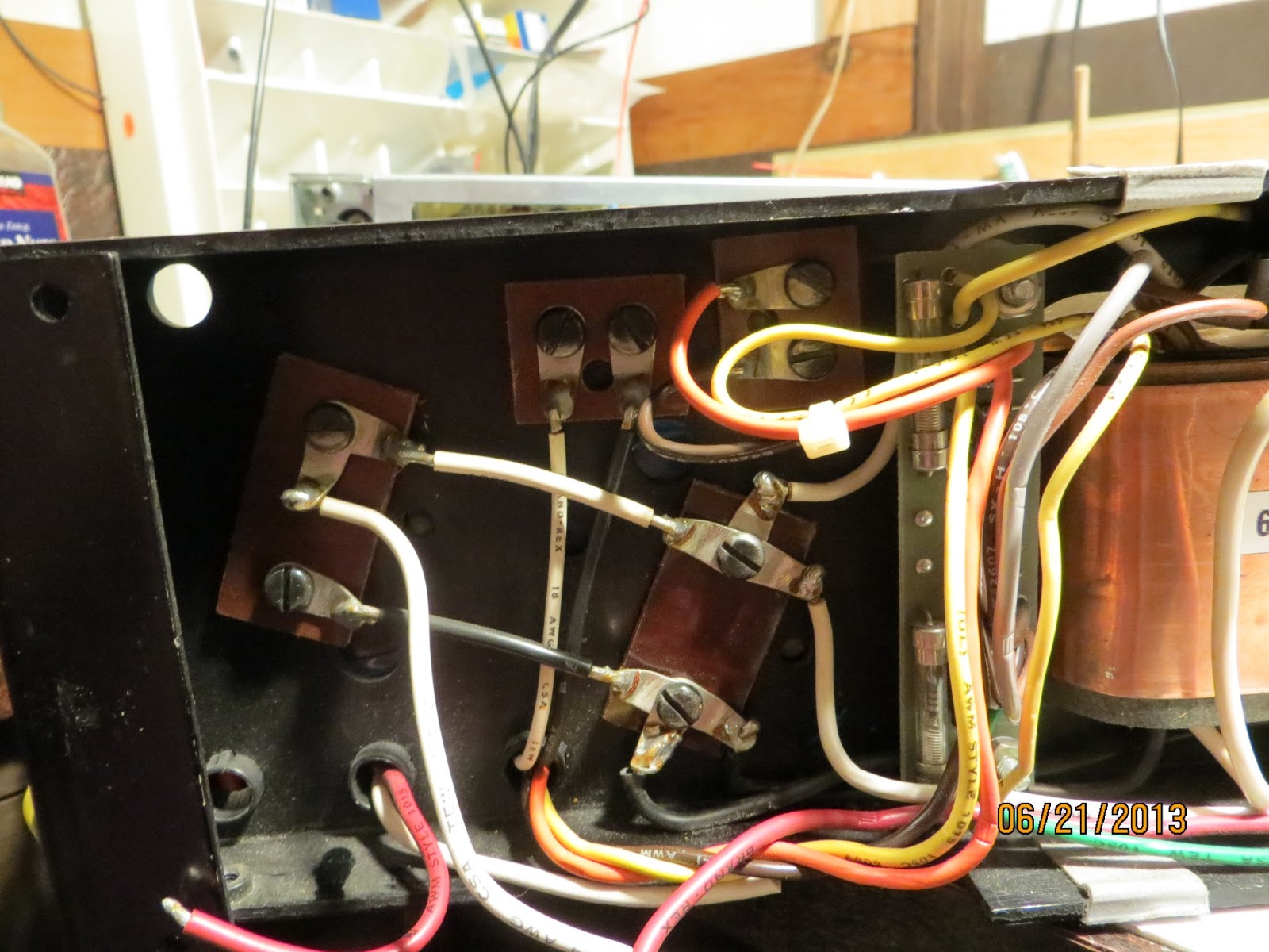
Wires ( red and white) to front fuse holder for both channel has to be cut ( i rather cut them than desolder because desoldering always over heat he wire and melt plastic covering of wires. Screw terminal caps are in 2 groups. 4 giant 30000uf 65v caps are main filter caps to feed 50v to current gain section ( output section) of amps and 2 small 1900 uf 100v are for feeding voltage regulators on the amp board and filter for after regulation circuit. I will replace 1900uf 100v caps even if they are still in good shape because safety factor for Modules.
By releasing wires that connect to fuse holders, amp board/ heat sink can be tipped over for work space. Desoldered 150uf 6v tantalum black Kermet caps ( these are keepers and applying wrong polarity to caps while even testing can destroy the caps) and ground wire to remove amp frame and amp board.
Removed amp board ( board with 4 black rectangular modules) and replace two 140 uf 40v caps with 220uf 100v caps which I had on hand. Now it is time to test amp for functionality.
I applied +-15 (+15 Ground -15) volt to wires that connected 1900uf caps ( White(+15)-blak&white(G)-Black(-15) to check out integrity of modules. I was extremely happy to see both channel having out puts on the scope without DC off set ( use DC coupling on osciloscope and see lines jump on the scope).
This means further disassembly of amp is in order. But before do that I decide to test current gain section of amp by applying +- 15 volt again. I snipped all four 300uf 70v rail caps which I will replace later. +15 volt was connected to red wire that connected to amp board and -15 was connected to white wire and ground to chassis ground. Left channel was good but right channel has DC off set and no signal out put. This means I lost at least predriver, and out put transistors. A channel of oscilloscope that connected to input pulse shows attenuation. This happens when a transistor which sits before + - rails separation goes shorted.
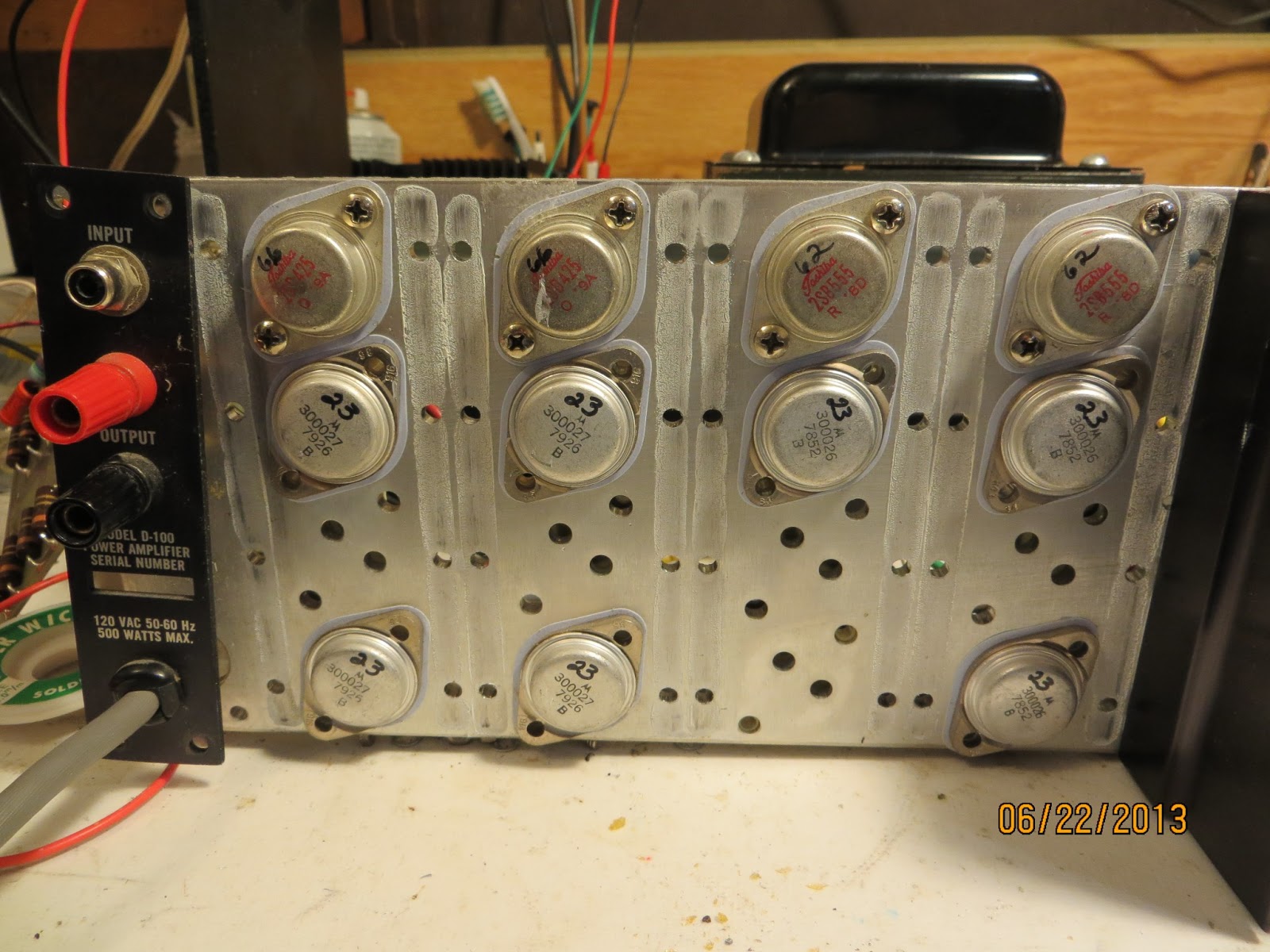
Emitter resistor boards need to be desoldered and removed to remove heat sink to gain access to TO-3 output devices. There are 4 matched complimentary pairs of Toshiba TO3 for pre drivers and eight total Motorola device for outputs. I usually cut the parts off before desolder when I replace the parts but to remove this board, I removed excess lead with vacuum pump then wick to clean off. Use extra soldering flux on the wick to reduce heat and increase wicking action. Remove excess rosin with dab of acetone soaked paper tissue.
One Toshiba TO3 and one Motorola TO3 went bad. This means I need to replace all 12 devices.
(Update)
Removing all TO3 are took little bit of time. I removed all the screws that hold TO3 first then desolder them so TO3 can drop down as desoldering become successful. There are few choices on TO3 device options out there. I decide to use MJ15024, MJ15025 combination and MJ21194, MJ21195 combo or just 15024 15025 for both pre and output depends on finding matching sets and data sheet comparison with Toshiba device. Out put devices on D-100b has number 300027 and 300026 on them which are Audio research internal numbers. I would not use used or new Chinese Toshiba devices. I am not so sure of authenticity of new old stocks on ebay.
Both channel rail caps been replace with 1000uf 100v radial caps. Before mounting amp board, I need to check r52, r54, r44, r46 to see if their value drifted. I do see little DC off set on the oscilloscope when I checked output section of left channel.
Left channel DC off set was higher than I thought. I have to desolder the emitter resistor board again to test all out puts and emitter resistors and bias resistors to see if any one of them is open to cause DC imbalance. DC off set is negative voltage so either one of predriver + side is open or - side pre driver is shorted. I have checked all the parts and I did not find any shorted or open parts. I am kind perplex on this issue. I might need to alligator clip the emitter board to find out which component is causing DC off set.
(update)
I am still having trouble with Dc off set. I am testing DC off set with external power supply ( uneven +- rail voltage ) +15 -13v. I literally checked every single components after Module #2. I replace all Toshiba pre drivers to MJ21195 MJ21196 pairs and all ARC internal numbered Motorola devices to MJ15024 MJ15025 sets. I am still getting close to + rail voltage on base of pre drivers. I need to investigate tonight to see what is causing the leakage there. I hade more complex repairs than this but this is the worst repairs I am experienced. It really is depressing to desolder and solder the board every time I need to inspect the board.
(update)
Somtimes, I am as dumm as broken amp. I should have just lift legs up of parts to test and look at the schematic to find out faulty parts before desolder and resolder entire board before mount. I switched polarity of rail caps - probably sleeping while soldering that on. Now I have two dead drivers on both chanel ( 1 pnp 1 npn) I should leave bias transistors alone on both channel while replaceing drivers if they are faulty. I want bias bjts (Q1 and Q4) match as close as possibly.


D-100B is the amp I am working on to add to my collection list. ARC D-100b has same circuitry as D-100 but it uses designer parts ( higher quality caps and resistors and bigger filter caps(?)) This amp weighs more than it looks because it is packed with big transformer and big size canned caps and milled heat sinks.
If you look at the schematic of Audio Research D-100B, it looks as if it has op-amps in their signal path. They are not op-amps they are custom made discrete solid state Analog Modules ( 1 and 2). Analog module 1 is buffer stage then Analog Module2 is voltage gain stage. These modules are cased in epoxy filled square block. If these modules are bad, you can not restore amp to original state period. I was hoping and praying for those modules to be fine when I purchased this broken amp.
1) Disassembly of Audio Research D-100B.
Amp was compact but it was heavier than my imagination. Once top cover and bottom cover are removed, screws on the side panels need to be removed to back portion ( heat sink and amp board).
Need to remove handles by removing screws from inside. Once handles are removed it is time to take some pictures of amp before snipping wires to disconnect amp parts.
Wires ( red and white) to front fuse holder for both channel has to be cut ( i rather cut them than desolder because desoldering always over heat he wire and melt plastic covering of wires. Screw terminal caps are in 2 groups. 4 giant 30000uf 65v caps are main filter caps to feed 50v to current gain section ( output section) of amps and 2 small 1900 uf 100v are for feeding voltage regulators on the amp board and filter for after regulation circuit. I will replace 1900uf 100v caps even if they are still in good shape because safety factor for Modules.
By releasing wires that connect to fuse holders, amp board/ heat sink can be tipped over for work space. Desoldered 150uf 6v tantalum black Kermet caps ( these are keepers and applying wrong polarity to caps while even testing can destroy the caps) and ground wire to remove amp frame and amp board.
Removed amp board ( board with 4 black rectangular modules) and replace two 140 uf 40v caps with 220uf 100v caps which I had on hand. Now it is time to test amp for functionality.
I applied +-15 (+15 Ground -15) volt to wires that connected 1900uf caps ( White(+15)-blak&white(G)-Black(-15) to check out integrity of modules. I was extremely happy to see both channel having out puts on the scope without DC off set ( use DC coupling on osciloscope and see lines jump on the scope).
This means further disassembly of amp is in order. But before do that I decide to test current gain section of amp by applying +- 15 volt again. I snipped all four 300uf 70v rail caps which I will replace later. +15 volt was connected to red wire that connected to amp board and -15 was connected to white wire and ground to chassis ground. Left channel was good but right channel has DC off set and no signal out put. This means I lost at least predriver, and out put transistors. A channel of oscilloscope that connected to input pulse shows attenuation. This happens when a transistor which sits before + - rails separation goes shorted.
Emitter resistor boards need to be desoldered and removed to remove heat sink to gain access to TO-3 output devices. There are 4 matched complimentary pairs of Toshiba TO3 for pre drivers and eight total Motorola device for outputs. I usually cut the parts off before desolder when I replace the parts but to remove this board, I removed excess lead with vacuum pump then wick to clean off. Use extra soldering flux on the wick to reduce heat and increase wicking action. Remove excess rosin with dab of acetone soaked paper tissue.
One Toshiba TO3 and one Motorola TO3 went bad. This means I need to replace all 12 devices.
(Update)
Removing all TO3 are took little bit of time. I removed all the screws that hold TO3 first then desolder them so TO3 can drop down as desoldering become successful. There are few choices on TO3 device options out there. I decide to use MJ15024, MJ15025 combination and MJ21194, MJ21195 combo or just 15024 15025 for both pre and output depends on finding matching sets and data sheet comparison with Toshiba device. Out put devices on D-100b has number 300027 and 300026 on them which are Audio research internal numbers. I would not use used or new Chinese Toshiba devices. I am not so sure of authenticity of new old stocks on ebay.
Both channel rail caps been replace with 1000uf 100v radial caps. Before mounting amp board, I need to check r52, r54, r44, r46 to see if their value drifted. I do see little DC off set on the oscilloscope when I checked output section of left channel.
Left channel DC off set was higher than I thought. I have to desolder the emitter resistor board again to test all out puts and emitter resistors and bias resistors to see if any one of them is open to cause DC imbalance. DC off set is negative voltage so either one of predriver + side is open or - side pre driver is shorted. I have checked all the parts and I did not find any shorted or open parts. I am kind perplex on this issue. I might need to alligator clip the emitter board to find out which component is causing DC off set.
(update)
I am still having trouble with Dc off set. I am testing DC off set with external power supply ( uneven +- rail voltage ) +15 -13v. I literally checked every single components after Module #2. I replace all Toshiba pre drivers to MJ21195 MJ21196 pairs and all ARC internal numbered Motorola devices to MJ15024 MJ15025 sets. I am still getting close to + rail voltage on base of pre drivers. I need to investigate tonight to see what is causing the leakage there. I hade more complex repairs than this but this is the worst repairs I am experienced. It really is depressing to desolder and solder the board every time I need to inspect the board.
(update)
Somtimes, I am as dumm as broken amp. I should have just lift legs up of parts to test and look at the schematic to find out faulty parts before desolder and resolder entire board before mount. I switched polarity of rail caps - probably sleeping while soldering that on. Now I have two dead drivers on both chanel ( 1 pnp 1 npn) I should leave bias transistors alone on both channel while replaceing drivers if they are faulty. I want bias bjts (Q1 and Q4) match as close as possibly.
(up date)
Because I replace all TO3's on right channel only for testing purporse, right channel runs much cooler than left which my guess has higher bias current. Bias current is set by two complementary Toshiba TO-3's. I replaced Toshiba TO3 to MJ21195 an Mj21196. I wil eventually replace all TO3 to improve saftey margin of operation.
Update 7/20/2013
Audio Research D-100b amp runs really hot. It is little to hot to touch with bare hand. The channel I replace all the TO3 runs some what cooler than original TO3 side. I have not checked bias current yet but I can bet it is biased to class a for sure with that kind of heat dissipation. It is really good sounding amp. It is as good as my Pass Clone amp ans runs as hot as it too.
Subscribe to:
Posts (Atom)