D-100B is the amp I am working on to add to my collection list. ARC D-100b has same circuitry as D-100 but it uses designer parts ( higher quality caps and resistors and bigger filter caps(?)) This amp weighs more than it looks because it is packed with big transformer and big size canned caps and milled heat sinks.

If you look at the schematic of Audio Research D-100B, it looks as if it has op-amps in their signal path. They are not op-amps they are custom made discrete solid state Analog Modules ( 1 and 2). Analog module 1 is buffer stage then Analog Module2 is voltage gain stage. These modules are cased in epoxy filled square block. If these modules are bad, you can not restore amp to original state period. I was hoping and praying for those modules to be fine when I purchased this broken amp.
1) Disassembly of Audio Research D-100B.
Amp was compact but it was heavier than my imagination. Once top cover and bottom cover are removed, screws on the side panels need to be removed to back portion ( heat sink and amp board).
Need to remove handles by removing screws from inside. Once handles are removed it is time to take some pictures of amp before snipping wires to disconnect amp parts.
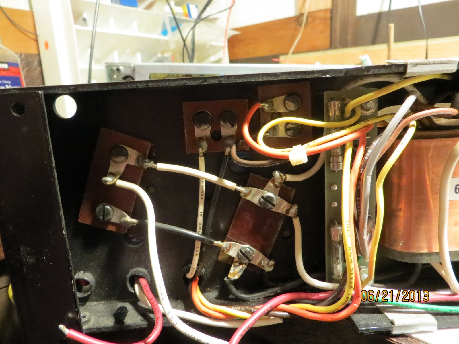
Wires ( red and white) to front fuse holder for both channel has to be cut ( i rather cut them than desolder because desoldering always over heat he wire and melt plastic covering of wires. Screw terminal caps are in 2 groups. 4 giant 30000uf 65v caps are main filter caps to feed 50v to current gain section ( output section) of amps and 2 small 1900 uf 100v are for feeding voltage regulators on the amp board and filter for after regulation circuit. I will replace 1900uf 100v caps even if they are still in good shape because safety factor for Modules.
By releasing wires that connect to fuse holders, amp board/ heat sink can be tipped over for work space. Desoldered 150uf 6v tantalum black Kermet caps ( these are keepers and applying wrong polarity to caps while even testing can destroy the caps) and ground wire to remove amp frame and amp board.
Removed amp board ( board with 4 black rectangular modules) and replace two 140 uf 40v caps with 220uf 100v caps which I had on hand. Now it is time to test amp for functionality.
I applied +-15 (+15 Ground -15) volt to wires that connected 1900uf caps ( White(+15)-blak&white(G)-Black(-15) to check out integrity of modules. I was extremely happy to see both channel having out puts on the scope without DC off set ( use DC coupling on osciloscope and see lines jump on the scope).
This means further disassembly of amp is in order. But before do that I decide to test current gain section of amp by applying +- 15 volt again. I snipped all four 300uf 70v rail caps which I will replace later. +15 volt was connected to red wire that connected to amp board and -15 was connected to white wire and ground to chassis ground. Left channel was good but right channel has DC off set and no signal out put. This means I lost at least predriver, and out put transistors. A channel of oscilloscope that connected to input pulse shows attenuation. This happens when a transistor which sits before + - rails separation goes shorted.
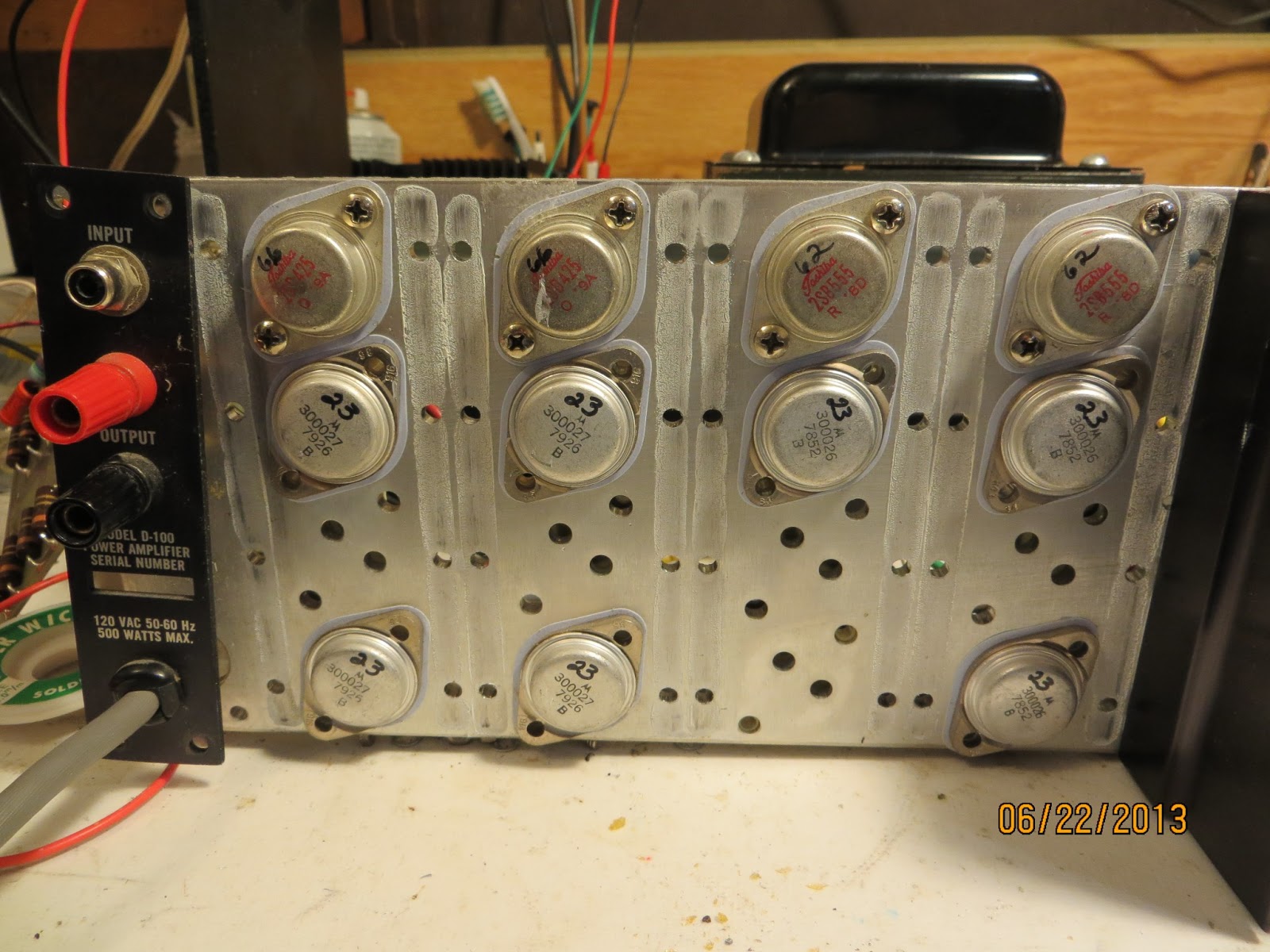
Emitter resistor boards need to be desoldered and removed to remove heat sink to gain access to TO-3 output devices. There are 4 matched complimentary pairs of Toshiba TO3 for pre drivers and eight total Motorola device for outputs. I usually cut the parts off before desolder when I replace the parts but to remove this board, I removed excess lead with vacuum pump then wick to clean off. Use extra soldering flux on the wick to reduce heat and increase wicking action. Remove excess rosin with dab of acetone soaked paper tissue.
One Toshiba TO3 and one Motorola TO3 went bad. This means I need to replace all 12 devices.
(Update)
Removing all TO3 are took little bit of time. I removed all the screws that hold TO3 first then desolder them so TO3 can drop down as desoldering become successful. There are few choices on TO3 device options out there. I decide to use MJ15024, MJ15025 combination and MJ21194, MJ21195 combo or just 15024 15025 for both pre and output depends on finding matching sets and data sheet comparison with Toshiba device. Out put devices on D-100b has number 300027 and 300026 on them which are Audio research internal numbers. I would not use used or new Chinese Toshiba devices. I am not so sure of authenticity of new old stocks on ebay.
Both channel rail caps been replace with 1000uf 100v radial caps. Before mounting amp board, I need to check r52, r54, r44, r46 to see if their value drifted. I do see little DC off set on the oscilloscope when I checked output section of left channel.
Left channel DC off set was higher than I thought. I have to desolder the emitter resistor board again to test all out puts and emitter resistors and bias resistors to see if any one of them is open to cause DC imbalance. DC off set is negative voltage so either one of predriver + side is open or - side pre driver is shorted. I have checked all the parts and I did not find any shorted or open parts. I am kind perplex on this issue. I might need to alligator clip the emitter board to find out which component is causing DC off set.
(update)
I am still having trouble with Dc off set. I am testing DC off set with external power supply ( uneven +- rail voltage ) +15 -13v. I literally checked every single components after Module #2. I replace all Toshiba pre drivers to MJ21195 MJ21196 pairs and all ARC internal numbered Motorola devices to MJ15024 MJ15025 sets. I am still getting close to + rail voltage on base of pre drivers. I need to investigate tonight to see what is causing the leakage there. I hade more complex repairs than this but this is the worst repairs I am experienced. It really is depressing to desolder and solder the board every time I need to inspect the board.
(update)
Somtimes, I am as dumm as broken amp. I should have just lift legs up of parts to test and look at the schematic to find out faulty parts before desolder and resolder entire board before mount. I switched polarity of rail caps - probably sleeping while soldering that on. Now I have two dead drivers on both chanel ( 1 pnp 1 npn) I should leave bias transistors alone on both channel while replaceing drivers if they are faulty. I want bias bjts (Q1 and Q4) match as close as possibly.


(up date)
Because I replace all TO3's on right channel only for testing purporse, right channel runs much cooler than left which my guess has higher bias current. Bias current is set by two complementary Toshiba TO-3's. I replaced Toshiba TO3 to MJ21195 an Mj21196. I wil eventually replace all TO3 to improve saftey margin of operation.
Update 7/20/2013
Audio Research D-100b amp runs really hot. It is little to hot to touch with bare hand. The channel I replace all the TO3 runs some what cooler than original TO3 side. I have not checked bias current yet but I can bet it is biased to class a for sure with that kind of heat dissipation. It is really good sounding amp. It is as good as my Pass Clone amp ans runs as hot as it too.
Have a fine sounding AR D100B amp to sell. 500.00 OBO
ReplyDeleteI want buy Analog Module type AM-2.
ReplyDeleteContact: hieubui212@gmail.com
Thanks!
nguyenphuc777@gmail.com
DeleteDid you find a fix for your DC offset issues? I have one on the bench now...Regards, AlleyGator
ReplyDeleteDid you ever find the problem?
DeleteHello do you have a Analog module-2 for sale? My Audio Research D-60 needs one. My email is lpskivor@gmail.com
ReplyDeleteThis comment has been removed by the author.
ReplyDeleteThis comment has been removed by the author.
ReplyDeletecan anybody give me any info on the d100 transistors 300025 or the cross
ReplyDeleteplease i really need some help on tran d100 amp 300025 pnp reach me at altenno@mail.com
ReplyDeleteI want to but analog module 1 , 1pc
ReplyDeleteWA:+6285363736004
Please info
Hey PlayAgainAudio are you still monitoring these posts on the AR D100B
ReplyDelete